Connector
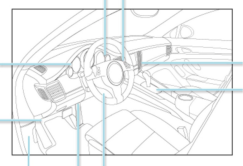
Access for OBD-II is the 16-pin OBD-II diagnostic socket in the vehicle, which is often used not only for the manufacturer-wide, exhaust-relevant OBD-II protocol, but also for the specific diagnostic protocols of the manufacturers.
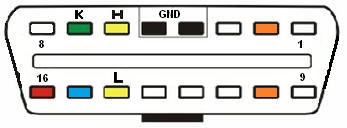
Male OBD connector assignment on diagnostic tool side
Female OBD connector assignment on the vehicle side
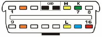
This is the theoretical pin assignment according to the OBD-II standard, the actual configuration with cables depends on which bus system the vehicle manufacturer uses for OBD-II.
| Pin | Description |
|---|---|
| 1 | Manufacturer-specific |
| 2 | J1850 Bus + (PWM, VPW) |
| 3 | Manufacturer-specific |
| 4 | Vehicle ground |
| 5 | Signal ground |
| 6 | CAN High |
| 7 | K-Line (ISO 9141-2) |
| 8 | Manufacturer-specific |
| 9 | Manufacturer-specific |
| 10 | J1850 Bus - (PWM) |
| 11 | Manufacturer-specific |
| 12 | Manufacturer-specific |
| 13 | Manufacturer-specific |
| 14 | CAN Low |
| 15 | L-Line (ISO 9141-2) |
| 16 | Battery (+) voltage |
With the introduction of the OBD-II for commercial vehicles, the problem arose that commercial vehicles operate with a 24 volt electrical network. Some OBD-II tools could not handle this higher supply voltage. The OBD socket "B" has been invented so that the tools are not destroyed. The slot in the middle is interrupted, so that an OBD connector of type "A" can not be connected.
Here the sockets in comparison::
- Type A is the original variant
- Type B the variant for supply voltages greater than 20 volts (according to standard)
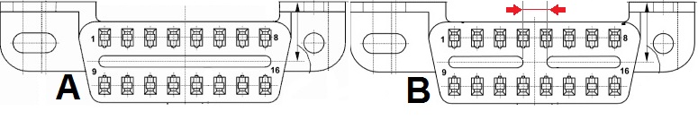
Conversely, the following can be said: If the bridge in the OBD connector of a diagnostic tool is interrupted in the middle, the tool is suitable for electrical network power supplies in the commercial vehicle sector.
There are different locations for the OBD socket in the vehicle